 Tweet
Tweet
Ok, so my other guitar player has finally flipped and wants to install LEDs inside his pickup cavity, but he has no idea on how to do it. I suggested he use a single LED to a AA battery box and wire it to an on/off switch. Anyone have any idea on where I can find a diagram to wire something like this? Or does anyone have any idea on how to wire something like this?
-
-
tell your guitar playing friend to take one step back from his guitar.......go sleep it off and come back tomarrow. "clean sounds are for pussies" - Axewielder
 -
Thanks that was helpful.Comment
-
LED's need a certain voltage and current, depending on the LED being used. You may need resistors to give it the proper amount of juice.
If you don't want an on off switch, you can use a stereo jack like EMG does, so that the LED's will be on only when the guitar is plugged in.Comment
-
when you're done, post the result 'cause
 Last edited by Nightbat; 01-24-2010, 01:53 AM."There's nothing taking away from the pure masculinity I possess"
-"You like Anime"
"....crap!"Comment
-
I'd go with a mercury switch, so as he rocks back and forth like Judas Priest the LED will come on and off in time with the rhythm. Jeez that would rock!_________________________________________________
"Artists should be free to spend their days mastering their craft so that working people can toil away in a more beautiful world."
- Ken MComment
-
LEDs require current limiting resistors, or else they will fail prematurely. Sometimes quite prematurely.
search for datasheets for the LED you intend to use. digikey.com is a good source for quick info if you don't have time to go thru manufacturer sites. Look for a parameter called "forward voltage drop" or sometimes labelled Vf.
You will also want to know the nominal operating current of the LED you choose. This is usally represented as Id in the datasheets. for small 5mm LEDs its usually around 20mA
Now that you have Vf and Id, you can calculate the resistor value you need by applying the concepts of Ohms law.
Battery Voltage - Vf - Id*R = 0
Where R is your resistor value. Choose R such that the equation balances out to zero. So, lets say for an example, your battery voltage is 4.5V. Your Id (diode current) and Vf (forward voltage drop of diode) is 2.7V. So 4.5v - 2.7v = 1.8v. You need to choose a resistor value such that R * Id = 1.8V. Or, in this example, R calculates to 90.0 but note that 90.0 is not a "standard" resistor value. 91 is the next closest standard value and will do nicely.
You see, the diode will always want to maintain a stable voltage drop across is (e.g. 2.7v typically). If you chose no resistor whatsoever, the leftover voltage (Vbattery - Vf) has no where to go in the circuit and will have to be dissipated in form of heat in the thinnest wire in the series circuit - which is usually an internal trace inside the LED itself. That is very bad for your LED.
Good luck! Post some pics when you're done, might turn out like a cool project.Last edited by maltomario; 01-23-2010, 11:46 PM.Proud endorser of:
Steve Clayton Inc. http://www.steveclayton.com
GLS Audio http://www.glsaudio.com
Orange County Speaker http://www.speakerrepair.com/Comment
-
Thanks for all the input guys. I did find a solution which will also not prematurely burn out the LED. It uses a single AA battery box to a SPDT switch to a 1.7V LED. I tested it and it works great, now just need to figure out where and how he wants this put into his guitar.
maltomario I do pose a question to you sir.
If I understand your explanation of resistance correctly I come up with the following:
1.5V-1.7-20mA*R=0
Wont I get a negative value in determining the resistance?Last edited by piranhaguy2002a; 01-24-2010, 12:01 AM.Comment
-
Hey, buddy http://jcfonline.com/forums/showthread.php?t=102310Originally posted by Nightbat View Post "Quiet, numbskulls, I'm broadcasting!" -Moe Howard, "Micro-Phonies" (1945)
Comment
-

Happy now?
 "There's nothing taking away from the pure masculinity I possess"
-"You like Anime"
"....crap!"Comment
-
Hey sorry for the late response. You will not get a negative resistance - if you do not have large enough voltage in your battery pack it will not turn on LED safely. in other words, Vbattery > Vf or else it is not designed properly.Originally posted by piranhaguy2002a View Post
If your diode Vf is 1.7v, you will need at least 2AA cells to turn it on since one AA battery is only 1.2 to 1.5V nominal voltage.
Be advised, just because LED lights up doesn't necessarily mean it is properly designed.Proud endorser of:
Steve Clayton Inc. http://www.steveclayton.com
GLS Audio http://www.glsaudio.com
Orange County Speaker http://www.speakerrepair.com/Comment
-
Cool, thanks for the clarification!!!Originally posted by maltomario View Post
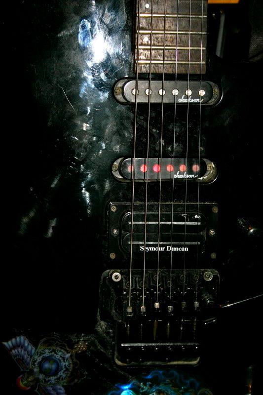
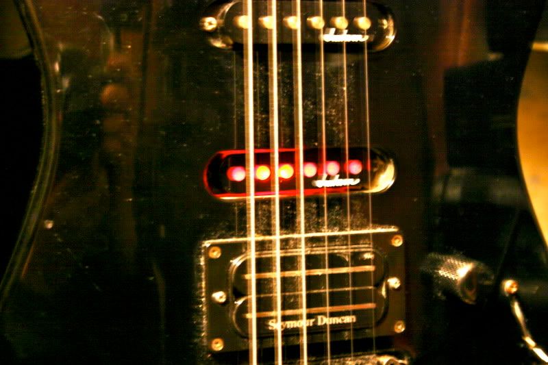
Looks like he's going to have this mounted in an unused middle pickup cavity. We're going to remove the pickup and keep the cover and mount the LED underneath the cover so the light shines through the empty pole holes. I'll post you guys some pics once it's complete.
Thank you all for your help and input!!!!!!Comment
-
I had an idea to do something similar, but never got around to it; basically lining the pup cavities with a bright paint (or aluminium tape), and mounting leds to the back of the pups. The leds wouldn't be directly visible, but the light would reflect off of the pup cavities. I think it would look wicked in the right conditions.Comment
-


Comment
-
That was fast! "Quiet, numbskulls, I'm broadcasting!" -Moe Howard, "Micro-Phonies" (1945)
Comment
Comment